Defining fractures
As the first step in hydraulic fracture modeling, use the Fracture Definition form (simulate > Hydraulic Fractures > Fracture Definition) to provide the basic settings (definition) for creating a tartan grid. Each tartan grid has a fracture definition that defines its creation. On the Fracture Definition form, you can make adjustments to an existing definition or create a new one.
-
In the Select fracture definition step, you create a new fracture definition or select an existing definition to modify.
- In the Area step, you can specify a new area using the Area Tool (click the
 icon to open this form) or edit an existing area. By default, an area is automatically generated for a new fracture definition.
 - The orientation of natural fractures is assumed to be parallel and/or perpendicular to the hydraulic fractures.
-
The sides of the Area box must be parallel to the orientation of the hydraulic and natural fracture planes. This means that you can either specify the orientation of the Area or the orientation of the hydraulic fractures.
If you want to use an Area box with a specific orientation, this fixes the orientation of the hydraulic fractures. See also the Update selected area from fractures option below.
If you want to specify a hydraulic fracture orientation, an Area box which aligns with the fracture orientation will be calculated.
- Select the wellbores that you want to include in the fracture model definition. You can quickly select all or clear your selections by right-clicking into the list and selecting the relevant option from the context menu.
- Specify the distribution of the hydraulic fractures along the wellbore.
- Deselect this option.
- Select only the wells in which you want to edit the fracture parameters in the list of Step 3. You can, for instance, edit the Distance between stages in Step 4 or select wells that had not been selected yet.
- Change the fracture parameter(s), if required.
- Click Apply.
Name Name of a new fracture definition to create.
Create Creates a new fracture definition. The new name appears in the Active field below. A default Area is created.
Active Name of the currently selected fracture definition. To work on another fracture definition than the currently active one, select the required fracture definition from the list.
Delete Deletes the current active fracture definition.
Copy from tartan grid Select to create a copy of the fracture definition of an existing tartan grid. Enter a name for the copied grid in the Name field.
Tartan grid Select the tartan grid whose fracture definition you want to copy.
Copy from active Select to create a copy of the currently Active fracture definition.
Copy Copies the fracture definition of an existing tartan grid or copies the currently active fracture definition. The copy is added to the Active list with the new name that you entered in the Name field, or, if you did not enter a new name, with the name that was in the Name field followed by a sequential number.
Be aware of the following relationships between the orientation of Area and fractures:
Area Select or define an Area for the active fracture model. When you specify a new fracture definition, a default area is created. You can edit the area graphically by moving the sides of the area box; alternatively click Edit to open the Area tool and specify the area parameters. Be aware that if the Update selected area from fractures option (see below) is selected, the area you specify here will be updated once you create the hydraulic fractures. The Area of a fracture definition will be used as the area for the tartan grid that is based on the fracture definition.
Surface Area The surface area of the current area box (read-only).
Update selected area from fractures Select to calculate an area around your wells and fractures. Specify the fracture azimuth and/or a minimum drainage area (see below). When you click Apply, the fracture model area is updated. After you have defined the area, deselect this option to prevent inadvertent changes. (Be aware that this means that you can no longer specify a fracture azimuth). The area you specify here for the fracture definition will be the area of the tartan grid.
Min. drainage surface area If you check the Update selected area from fractures check box, you can enter a minimum drainage surface area as a numerical value. This minimum area is used to calculate a surface area around the wells and fractures.
Fracture azimuth The orientation of the hydraulic fractures with respect to the North. If you check the Update selected area from fractures check box, you can specify a fracture azimuth value. When you click Apply, a default surface area around the wells and the fractures is calculated that is lined up with the fracture orientation. With the Minimum drainage surface area value, you can control the actual dimensions of the area.If you don't check the Update selected area from fractures check box, you cannot set a fracture azimuth and the fractures will be oriented in line with the currently selected area box.
Use perforation centers When selected, the fracture model takes the center of the (existing or planned) perforation interval(s) as the position where the hydraulic fractures occur. Perforations can be created in the Wellbore view or in the Well Planning / Well Markers and Perforation Editing workflow form. If you select this option, the options Distance between stages, MD offset well target zone entry and MD offset well target zone end are no longer applicable.
Specify stage distance When selected, the fracture model positions the hydraulic fractures with a constant spacing along the borehole.
Distance between stages The spacing between successive hydraulic fracture locations. This option applies to Specify stage distance and is not accessible when you select Use perforation centers. After you create the fracture definition, you can change the position of individual fractures in the Hydraulic Fracture view.
MD offset well target zone entry Distance along the borehole from the point where the well enters the target zone. The offset point marks the start of the well’s MD interval in which hydraulic fractures are created. This option applies to Specify stage distance and is not accessible when you select Use perforation centers.
MD offset well target zone end Distance along the borehole in front of the point where the well exits the target zone, or, if the well stays in the target zone, before the well’s toe. The offset point marks the end of the well’s MD interval in which hydraulic fractures are created. This option applies to Specify stage distance and is not accessible when you select Use perforation centers.
Replace existing fractures (Default option) When you change anything in the fracture definition the entire fracture definition is updated in all wells. If you deselect wells in Step 3, they are removed from the fracture definition. If you don't select this option, you can update fracture parameters for a selection of the wells in the existing fracture model only, or add wells to the fracture definition. To do so:
Only the fracture definition in the selected wells are updated, and new wells, if selected, are added; in the other wells the fracture definition remains unchanged.
Specify the hydraulic fracture properties which define the area around the fracture that will be stimulated. The settings you define here are defaults for all fractures. You can edit the properties of individual fractures in the Hydraulic Fracture view.
Half length Lateral extent of fracture from wellbore (see image below).
Height Total vertical extent of fracture(see image below).
Width Width of the fracture.
Permeability Permeability of the hydraulic fractures.
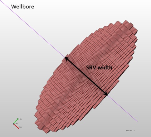
SRV width click to enlarge
SRV width Width of the Stimulated Reservoir Volume, i.e. the width of the area around the hydraulic fractures which is affected by the hydraulic fracturing, both by inducing new fractures and by opening (or closing) natural fractures(see image). How and to what extent the natural fractures contribute to simulation depends on the Natural fractures settings.
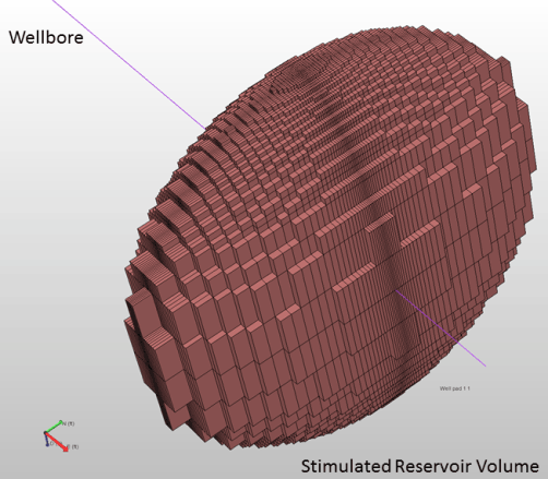
Strimulated Reservoir Volume click to enlarge
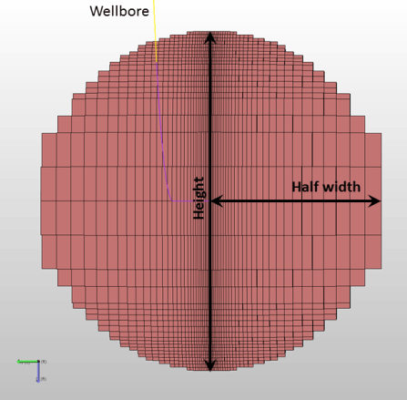
Fracture height and half width click to enlarge